What is camera sensor tilt?
This year marks my 6th year into the astrophotography hobby. Just about every camera I’ve owned has suffered from some kind of sensor tilt. Mass manufacturing methods without a good QC process inevitability end up with sensor tilt in the sensors. Sensor tilt occurs when the sensor is not orthogonal to the imaging plane. The sensor itself is not 100% level across the face of the camera, and is slightly tilted. In many cameras this is never noticeable when taking pictures of every day objects. In astrophotography, where we’re photographing stars that are expected to look like tiny points of light, this usually appears across your images by having slightly elongated or strange shaped stars on one side or corner of the images you take.

Here you can see a single frame of Caroline’s Rose shot on the Esprit 100 with a ZWO ASI2600MC-Pro camera. Notice the tilt in the lower right hand corner.
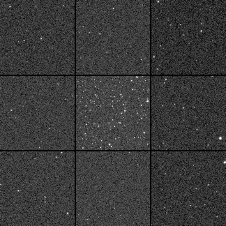
I’ve used the Aberration Inspector within PixInsight to create a grid of all corners, sides and center of the image to show how the stars look across the frame. This is a single frame of Caroline’s Rose shot with the Esprit 100 and a ZWO ASI2600MC-Pro camera. I debayered the color image, extracted the luminance and run the script on the stretched image to show these results. This amount of tilt is how the sensor came from the manufacturer and has had no adjustments applied to correct for it.
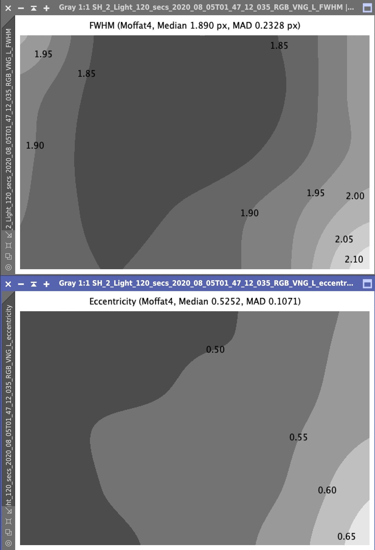
In this next set of images I show the FWHM Eccentricity calculations for the tilted image. FWHM in the top part of the image shows how in focus each area of the frame is, and you can see towards the bottom right of the frame the stars are less in focus. The same goes for the Eccentricity plot. Eccentricity is how round your stars are across the image. Very round in the upper left, and not so round in the lower right. A clear case of tilt in the image.
Just to be clear though, tilt in your images can come from many things. Sag, due to heavy weight of your image train, a poorly collimated focuser, mirror shift in a reflector where the primary mirror isn’t locked down, and also from a non-orthogonal image sensor.
This method of collimating your sensor will only remove sensor tilt. And there are variations of this method which can remove tilt from your entire system assuming you have rigid, threaded connections through quality parts of your imaging train.
How do we get rid of the tilt?
One way to do this, and the reason it’s taken me 6 years before attempting tilt removal, is to shoot images of an area of the sky with lots of stars, then make adjustments to your tilt adjuster, and take more images to see how things have changed with your image after making the adjustment. There is some software that can aid in helping you do this. You will read about many people attempting this method which is fraught with frustration. Hair-pulling frustration…while trying to correct for this under the stars in the dark of your back yard. In my case, during the summer months, mosquito-infested sweltering-heat which only makes the process less tolerable. So I just lived with the issue.
Being a perfectionist though, and finally finding a method to do this indoors, I’ve undertaken the steps to remove tilt from my cameras after 6 years. StarlightXpress published an article on their website showing a camera collimating rig they made. The advent of this post, and a thread on Cloudy Nights along with support in that thread from (@Peter in Reno, @rockstarbill, @corpze and others) got me heavily involved in this process. You’re welcome to sort through the gory details of that thread as we work through the issues of creating the rig, and troubleshooting how to make the adjustments, but I’m about to outline them below.
The camera sensor collimating rig
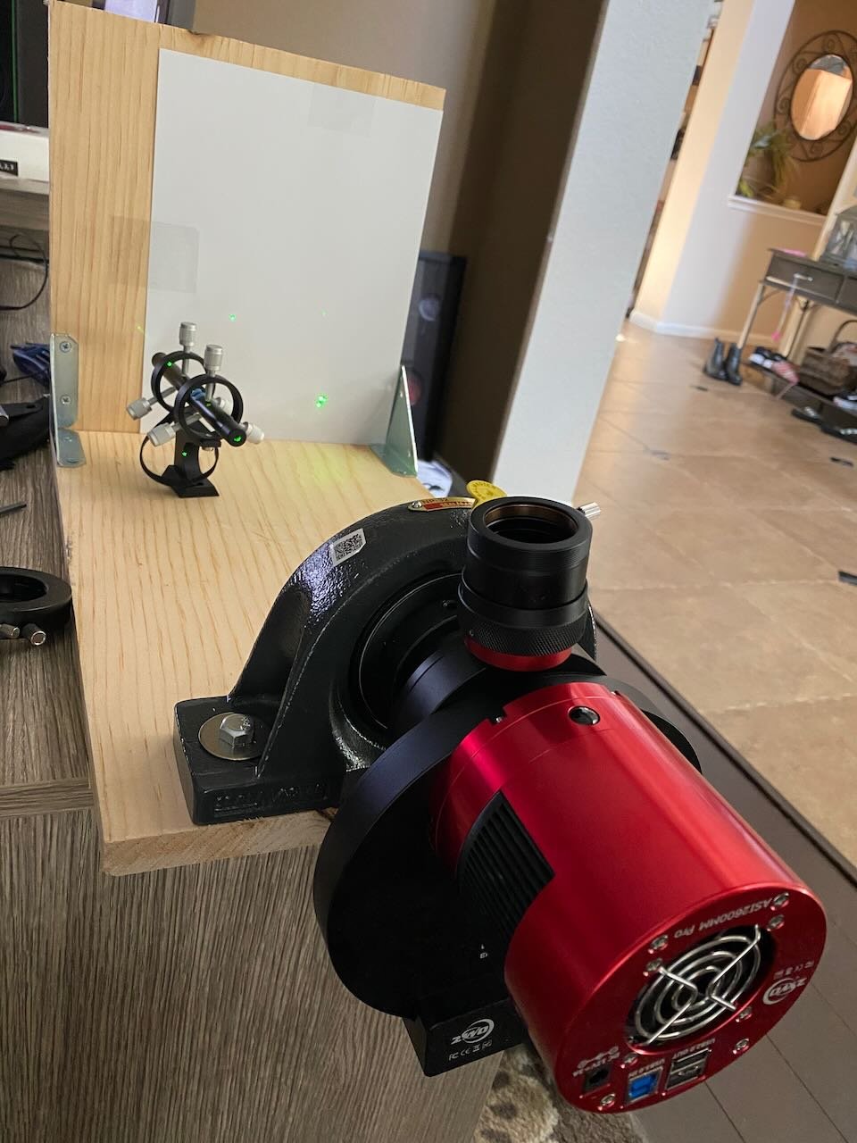
This rig, allows you to mount the camera from the tilt adjuster back in a rotating device (in this case it’s a mounted bearing with a 2” inner diameter), and shine a laser at the sensor window which reflects a grid of the sensor pixels, sensor cover slip window, and sensor window itself onto a flat surface. By rotating the camera, and making adjustments to the tilt adjuster you can effectively remove all tilt from your camera sensor.
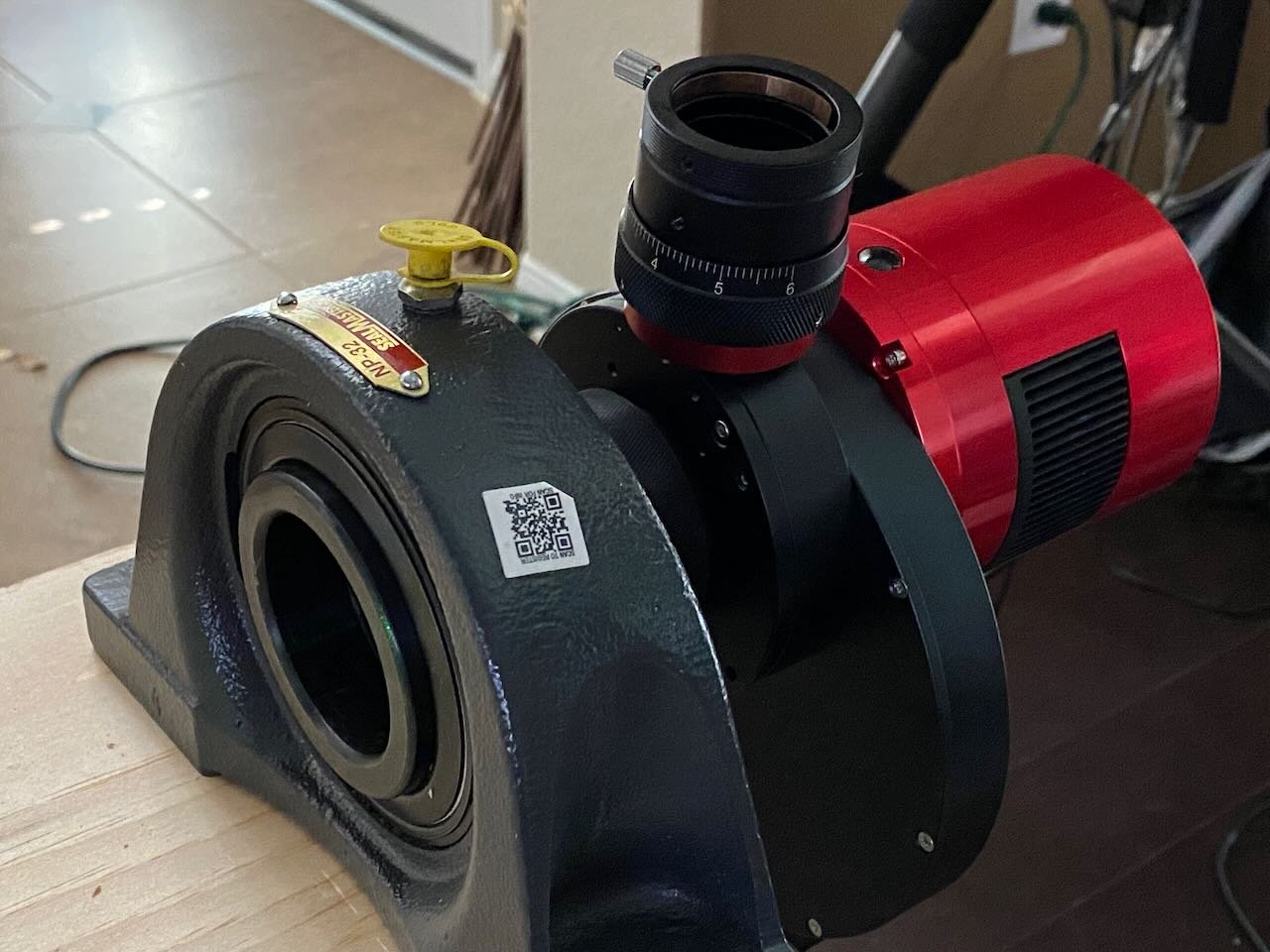
The 2” nosepiece is attached to the tilt plate. In a mono ZWO setup as shown in the image, the tilt plate is in front of the OAG. In a color camera setup, the tilt plate is attached to the camera directly. Other brand cameras or some cameras don’t include tilt plates, and one has to be purchased and accounted for in your imaging train or you cannot make tilt adjustments. Gerd Neumann makes a CTU tilt plate that many like for it’s ease of adjustment.
I built this with parts available from the hardware store and internet, and it’s pretty straight forward. It took me about 15 minutes to build once I had the parts in place.
Shopping list:
11 1/4 in. x 3/4 in. x 8 ft (standard shelf board or plywood) available in the lumber section of the hardware store
Mounted Steel Ball Bearing with Cast Iron Housing for 2" Shaft Diameter, with Set Screw
Two 2” self taping wood bolts with 1” washers to bolt down the bearing.
Tilt plate adjuster (either built into the camera, or purchased separately)
This was the parts list for my setup, and the mounted steel ball bearing is very expensive at $250 or so. You don’t need this at all. There’s a way simpler and cheap method for accomplishing the same thing, but this is the part that I bought before discovering there was a cheaper way to do this. I found that my Moonlite 2” compression ring and some tube extenders I had laying around could have accomplished the same thing for effectively free.
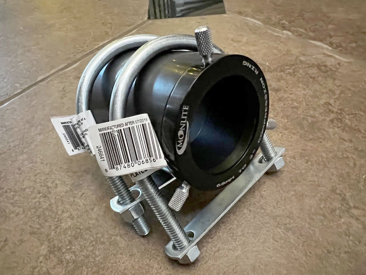
As an alternative to the bearing I used, you can purchase some “2-3 in. U-Bolts” to fit a 2” compression ring with some spacers attached. You need enough spacers attached to extend the barrel so that it can be bolted down to your wood shelf.
Assemble your rig
Building the rig is very simple. Just look at the photo above of the completed rig. Saw your board into a few pieces, you’ll have more than enough. I would make the bottom piece around 24 inches. And the top board only needs to be tall enough to hang a sheet of paper on it (or not). I found the paper made it easier to see the reflected dots, and you can mark their position on the paper with a pencil to help in collimating/adjusting tilt. Your corner brackets help hold the vertical board, and the bolts are for bolting down the bearing or 2” compression ring tube.
How to remove your sensor tilt
Now for the final steps.
Remove your camera assembly from your telescope at the tilt plate back to the camera.
Thread the 2” nose piece adapter on to the tilt plate.
Insert the nose piece/camera assembly into the bearing, or compression ring and lock it down so it doesn’t fall out. If you have a camera assembly with filter wheel, just hang the edge of your rig over the end of a table so you can fully rotate the camera assembly in the bearing.
Turn on the laser, and shoot it through the open end of the assembly at the camera sensor.
Move the laser around to adjust the projected reflection on the back board so that you can see not only the pixel grid reflected, but the two bright reflections from the sensor glass and sensor protection window. (Note: you can peek your head and look through the barrel, try to aim your laser towards the center of your camera sensor or just off to one side, making sure if you rotate the assembly in place the laser doesn’t go off the short edge of the sensor.)
Here’s a detailed view of the array of reflections.
You will notice as you rotate your camera assembly in the bearing or compression ring (you’ll have to unlock it to do this), you’ll see a series of reflections detailed above. All these reflections will rotate in circles. The only reflection you care about in this scenario is the pixel reflection closest to the two bright reflections of the sensor windows. Try and ignore the glass window reflections, and as you rotate the camera you will notice that sometimes the glass reflections will overlap the pixel reflection.
The goal here is to rotate and make tilt adjustments until the collimation pixel reflection becomes stationary and rotates in place (no longer in a circle). At this point, your tilt has been removed using your tilt adjuster.
Final Sensor collimation steps:
With the reflections in plain view as shown above, rotate until the collimation pixel is at the furthest point to the right and hold the camera steady or lock it down.
Now look at your camera from behind. You want to adjust (outward) the tilt screws that are on the opposite side of the camera from where the pixel is.
We’ve moved the pixel to the right most point by rotating the camera, so we’re going to adjust outward the tilt screws furthest left on the camera when looking from the rear. That should pull that right most pixel towards the center, making the circle of rotation smaller.
Continue to rotate the camera making minor adjustments until you get that collimation pixel as stationary as possible.
Your results should start to look like the above video. I still have a very small adjustment left to make as my collimation pixel is still making a tiny circle.
The slower your scope F rating is, the far more forgiving the results are. At F7-10 this result is good enough. At F2-3, you will need to continue to dial it in until there is no circular movement. At higher F speeds the tiniest amount of tilt will still show in your imaging results.
The final results
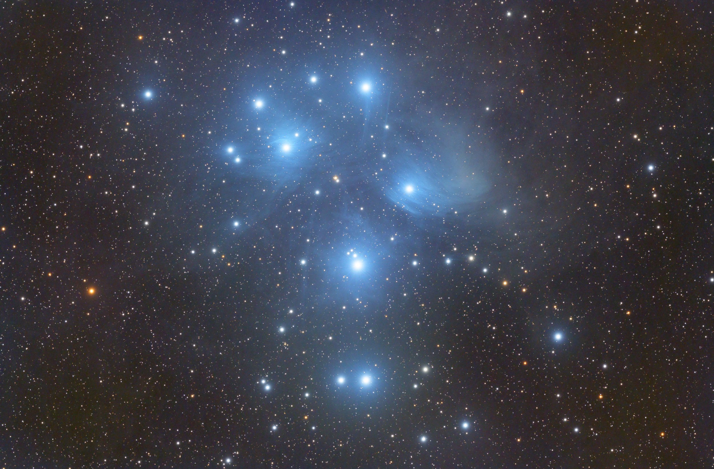
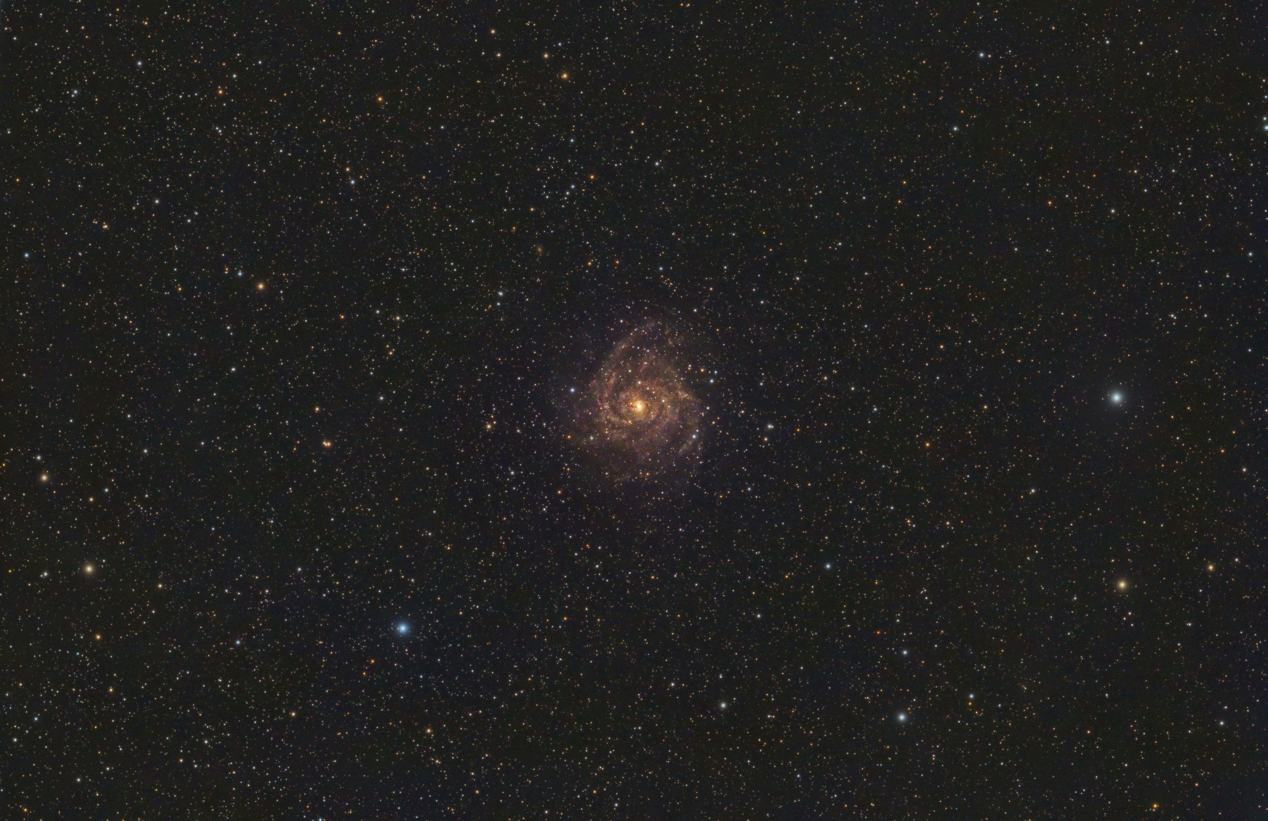
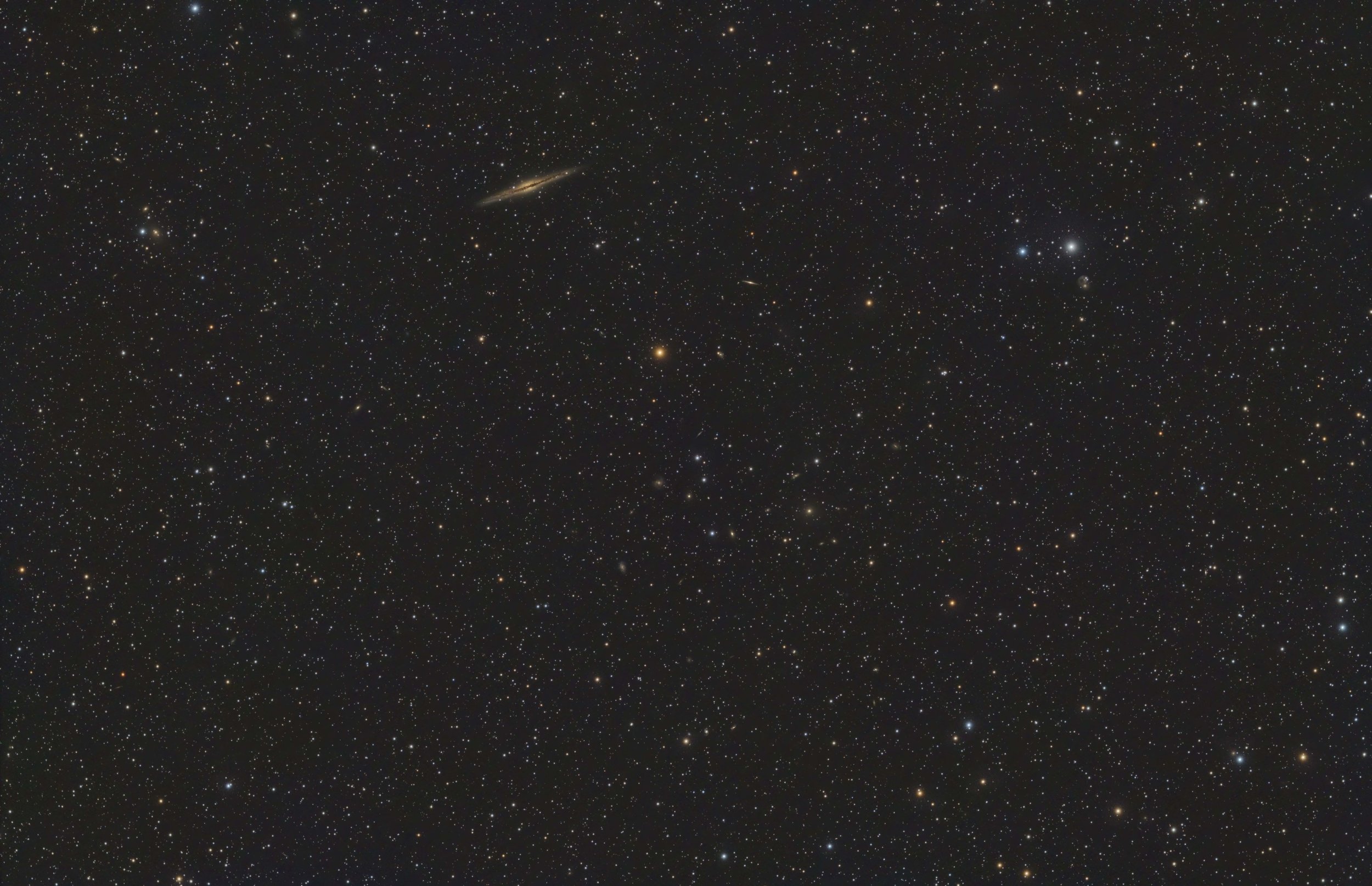
Here you can see the results of the collimation rig. This is Caroline’s Rose on the same telescope and camera for the starting shot. Now tilt is fully removed. Stars are perfect on all four corners across the frame. Here are some recent images I’ve shot with the Esprit 100 and the tilt adjusted ZWO ASI2600MC-Pro camera.